This website uses cookies for a better browsing experience.
If you agree to the use of cookies, please click the "Agree" button.
Please refer to the Privacy Policy regarding the use of cookies on this site.

Contact Us
Select Your Country
It all started with a small wooden bearing.
PRODUCTS

How to replace (install and remove) an Oiles bearing (plain bearing)

Installation

Installation (press-fitting)

Install (press-fit) using hydraulic pressure, pneumatic pressure, or a vise.

  • Press-fitting with force, such as hammering, will result in bearing damage or a change in its bore.
    When installing, use the recommended tolerance (H7) for the dimensions of the housing bore as shown in the catalog.
  • #500SP1 SL1 spherical bearing (SPS): K7 (general use), N7 (high loads)
    #2000 high-precision bearings (CLB and CLF): H6

When replacing a bearing in a blind hole, the design of the surroundings must take removal into consideration.
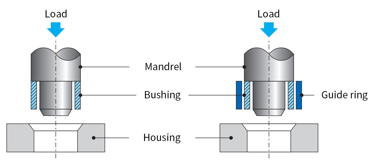
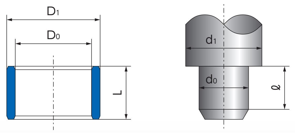
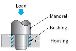
Press-fitting jig

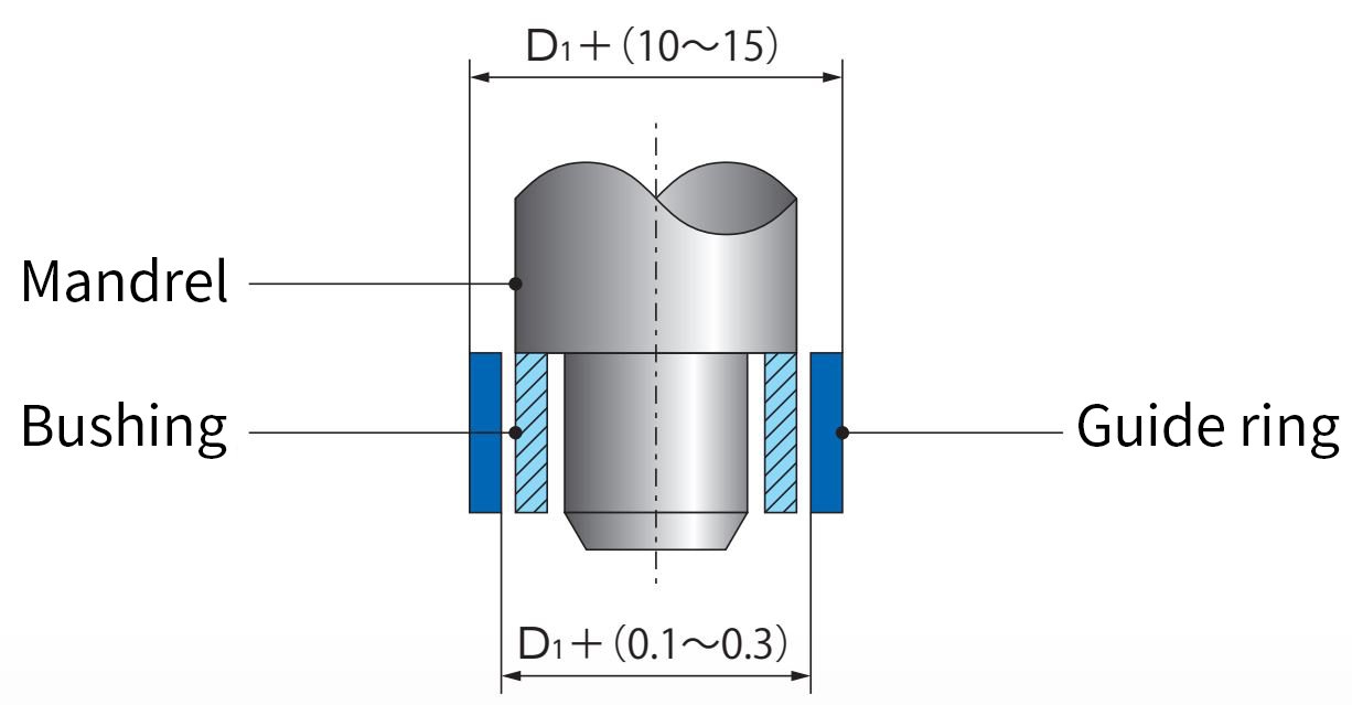
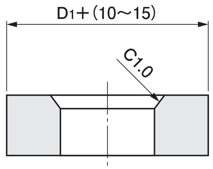
In general, use a mandrel to insert the bushing in the insertion site in the housing as shown in Figure 1.
The use of a guide ring, as shown in Figure 2, facilitates press-fitting.
The use of a guide ring is effective at ensuring the roundness and centering of the bore after press-fitting and in preventing damage to the bushing during press-fitting.

Figure 1 Typical press-fitting Figure 2 Press-fitting with a guide ring

Figure 1 Typical press-fitting Figure 2 Press-fitting with a guide ring

  • To facilitate press-fitting of the bushing, the edge of the housing bore should be chamfered where the bushing will be inserted.
    The housing should have an R chamfer or a tapered chamfer.
    If it has a C chamfer (C1.0 or less), make sure there are no burrs. The use of oil or grease can facilitate press-fitting.

Mandrel dimensions should be determined based on the table below.

Bushing dimensions (nominal)Mandrel dimensions
Inner diameter(D0)d0=D0-(0.05~0.10)
Outside diameter(D1)d1=D1-(0.20~0.30)
Length(L)ℓ≧L

Figure 3 Mandrel dimensions

Guide ring dimensions should be determined based on the table below.

Bushing inner diameterGuide ring inner diameterGuide ring outside diameter
Φ40D1+(0.1~0.3)D1+(10~15)
Φ42~φ60D1+(0.2~0.5)
Φ65~D1+(0.5~1.0)

The inner diameter of the guide ring should be large enough to allow gentle press-fitting of the bushing by hand.
The length of the guide ring should be at least 1/3 of the length of the bushing. If possible, it should be the same length as the length of the bushing.

Figure 4 Guide ring dimensions

When using a screw on a metallic bearing to prevent loosening or turning

A screw to prevent loosening and turning must be installed in a position away from load points. After the bearing is set in the housing, a locking screw with a diameter equivalent to the thickness of the bearing wall should be machined at a position towards the housing by about 20 to 30% of the screw diameter as shown in Figure 5.
An end mill should be used when machining holes.

Figure 5 Position to prevent turning (reference image)

Removal

When using a screw on a metallic bearing to prevent loosening or turning

After removing the screw, the bushing can easily be removed using a mandrel in the same manner as during press-fitting.

Removal jig (for a through hole)

Figure 6 Mandrel dimensions